Solder Heat Resistance Test (SHRT)
The Solder Heat Resistance Test (SHRT) determines whether semiconductor device terminations can withstand the effects of heat at the level they will be subjected to during the soldering process. In the lifetime of the device it can experience heat conducted through the termination, as radiant heat from the solder bath when in close proximity to the body of the device or both.
ORS uses a solder dip method to simulate the conditions encountered in wave soldering for both radiated and conducted heat. We have three different methods of performing this test:
- Test Condition A: We place the tip of a soldering iron to the area of the assembly closest to the device body. For surface mount devices, the iron is placed on the pad only.
- Test Condition B: We dip the terminations into the solder pot within 0.050 inches of the device body, in what is called the solder dip method. The fixture shall be made of a non-solderable material and have minimal contact with the device.
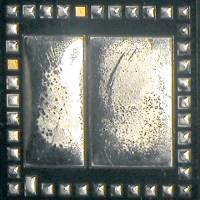
- Test Condition I, J, and K: This method uses a convection/conduction reflow oven by placing the parts onto an FR-4 base material in accordance with ASTM D1867. The device is placed on pads large enough to accommodate the test device and requires three passes through the reflow oven. This method is preferred for leadless chip carrier (LCC) devices.
- Test Specifications / Standards
- MIL-STD-750 Method 2031
ORS examines devices under 10x magnification in all three test methods. We also conduct internal examination after the test, upon request, to check for solder reflow or heat damage.


